MIL-DTL-27188C
LAMPS
5V
E
400
BLUE
D
D
S1
YELLOW
C
C
S3
RED
B
B
R1
S2
S
R2
BLACK
2
A
A
TRANSMITTER
INDICATOR
26V 400
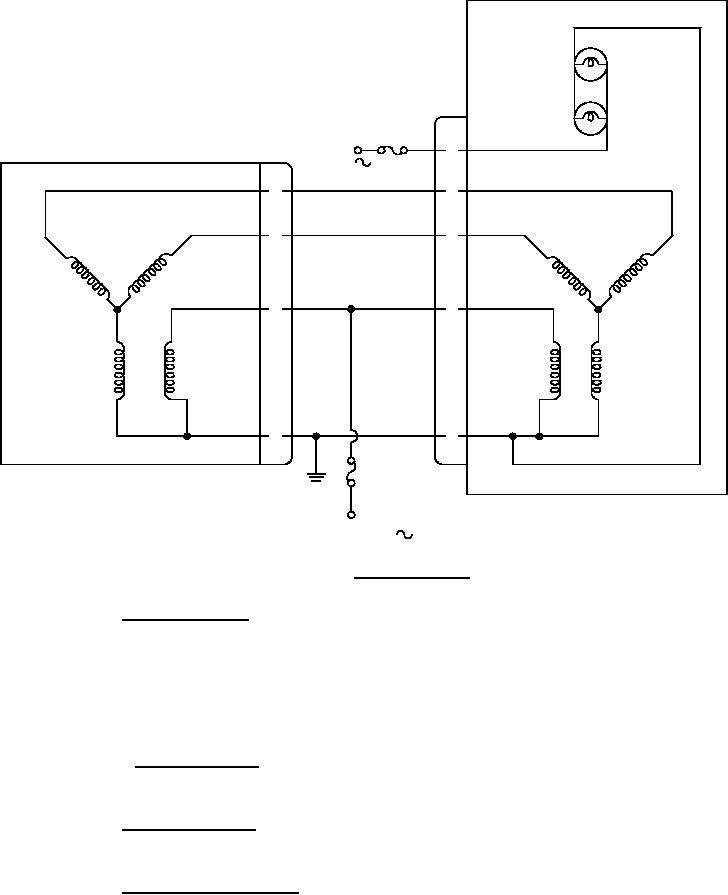
FIGURE 2. Wiring diagram.
3.3.11 Indicator synchro. The indicator synchro shall consist of a salient two-pole wound
rotor used as the primary and shall be designed for 26 volt (V), 400 cycle, single-phase power, with
Y-connected stators as the secondaries. The stators shall be wound so the amplitudes of the
induced voltages measured between any two stator leads will vary approximately sinusoidally with
the angular positions of the rotor. Pivots, bearings, and gears shall not bind or shake and shall be as
nearly frictionless as possible.
3.3.11.1 Synchro receiver. The synchro receiver used shall have electrical characteristics
compatible with those defined in SAE AS20708.
3.3.12 Secondary voltage. The maximum open-circuit voltage measured between any
two secondary leads shall be 11.8V ± 3 percent.
3.3.13 Radio noise interference. The indicator shall meet the radiated and conducted
radio noise interference requirements of MIL-STD-461.
8
For Parts Inquires call Parts Hangar, Inc (727) 493-0744
© Copyright 2015 Integrated Publishing, Inc.
A Service Disabled Veteran Owned Small Business