MIL-DTL-38394E
TRANSMITTER
BC
BC
AD
AD
INDICATOR
FUSE
26V 400HZ
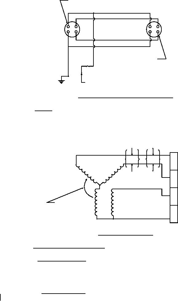
FIGURE 2. Wiring diagram - external, single indicator.
3.9.2 Internal. Internal wiring of the transmitter shall be color coded and shall be
connected to the receptacle pins as shown in figure 3. When gears are used to drive the transmitter
counterclockwise for increasing values of the parameter being measured, terminals S1 and S3 shall
be reversed internally to cancel the effects of the gear reversal to ensure clockwise rotation of the
indicator synchro shaft and pointer with increasing values.
BLUE
YELLOW
OR
D
YELLOW
BLUE
C
RED
B
DIRECTION OF
ROTOR ROTATION
FOR INCREASING
A
PRESSURE
BLACK
FIGURE 3. Internal electrical circuit.
3.10 Finishes and protective coatings.
3.10.1 Aluminum alloy parts. Aluminum alloy parts shall be coated with an anodic film
conforming to MIL-A-8625, except the small holes, straight threads, case inserts, and parts in the
sealed enclosure. Aluminum alloys that do not anodize satisfactorily shall be coated with a
chemical film conforming to MIL-C-5541.
3.10.1.1 Abrasion resistance. When abrasion resistance is a factor, chemical film in
accordance with MIL-DTL-5541 shall not be used in lieu of anodizing.
10
For Parts Inquires call Parts Hangar, Inc (727) 493-0744
© Copyright 2015 Integrated Publishing, Inc.
A Service Disabled Veteran Owned Small Business