MIL-DTL-83361B
3.3.7 Fasteners. The dial shall be securely fastened to the frame of the mechanism in
such a manner that it will not loosen or turn when the indicator is vibrated. If screws are used
for attaching the dial, they shall be located in a position where they do not interfere with the dial
markings or prevent the markings from being located in the proper position.
3.3.8 Electrical zero reference mark. The dial shall be provided with an electrical zero
reference mark on the scale portion equidistant in angular degrees between the first and last
graduations.
3.3.9 Electrical connector. The indicator shall be provided with an electrical connector
in accordance with figure 1. When the connector is nonhermetically sealed, a hermetically
sealed baffle plate shall be used to seal the indicator.
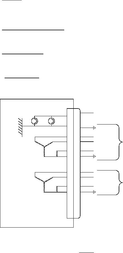
3.3.10 Electrical wiring. The wiring of the indicator shall be in accordance with figure 3.
The indicator wiring shall be designed so that no portion of the internal circuitry will be connected
to the instrument case except the ground wire of the lighting circuit.
5 V LIGHTING
K
J
LAMP (TYP)
BLUE
S1
H
YELLOW
RIGHT TRANSMITTER
G
S3
RED
R1
REAR SYNCHRO
26 V, 400 Hz
F
E
S2
R2
BLACK
BLUE
S1
D
YELLOW
C
S3
LEFT TRANSMITTER
RED
R1
FRONT SYNCHRO
26 V, 400 Hz
B
A
S2
R2
BLACK
NOTE: Pin J of the lighting circuit shall be internally connected to the instrument case.
FIGURE 3. Wiring.
8
For Parts Inquires call Parts Hangar, Inc (727) 493-0744
© Copyright 2015 Integrated Publishing, Inc.
A Service Disabled Veteran Owned Small Business